Goal
Connect the wiring to interface the keypad with the microbit
Set your own unique password for the lock
Add a lock down counter in case an intruder tries to guess your password

Connect the wiring to interface the keypad with the microbit
Set your own unique password for the lock
Add a lock down counter in case an intruder tries to guess your password
1 x Breakout board
1x Micro:bit
1x Mini Servo
1x Breadboard
4×4 Membrane keypad
3x 5kohm resistor
3x 1kohm resistor
1x 10kohm resistor
Jumper Wires
1x OLED
18.5cm x28cm Acrylic
1x small Metal Hinge
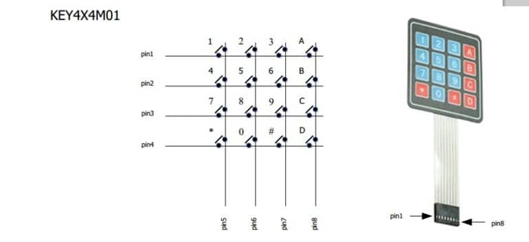
The membrane keypad has 16 different switches which have 16 different characters
The switches are grouped together by row and column for example (R1,C1) corresponds to 1 and so on.When the controller detects a 1 at Pin 1 and Pin 5 it would mean key 1 is pressed.This is called digital output
Therefore we can use the Microbit’s digital pins to interface with they keypad.However if we do that it will be quite messy.
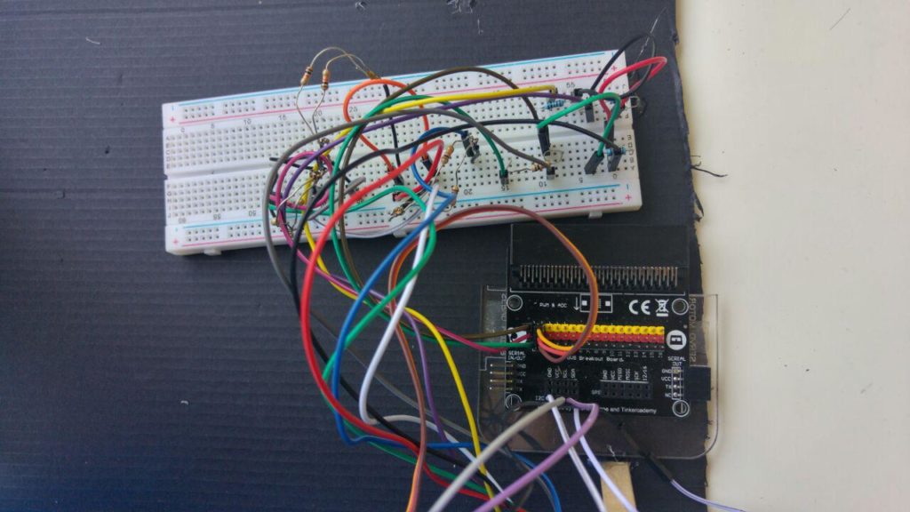
Lets create a driver circuit for the 4×4 keypad!
Follow the diagram as shown:
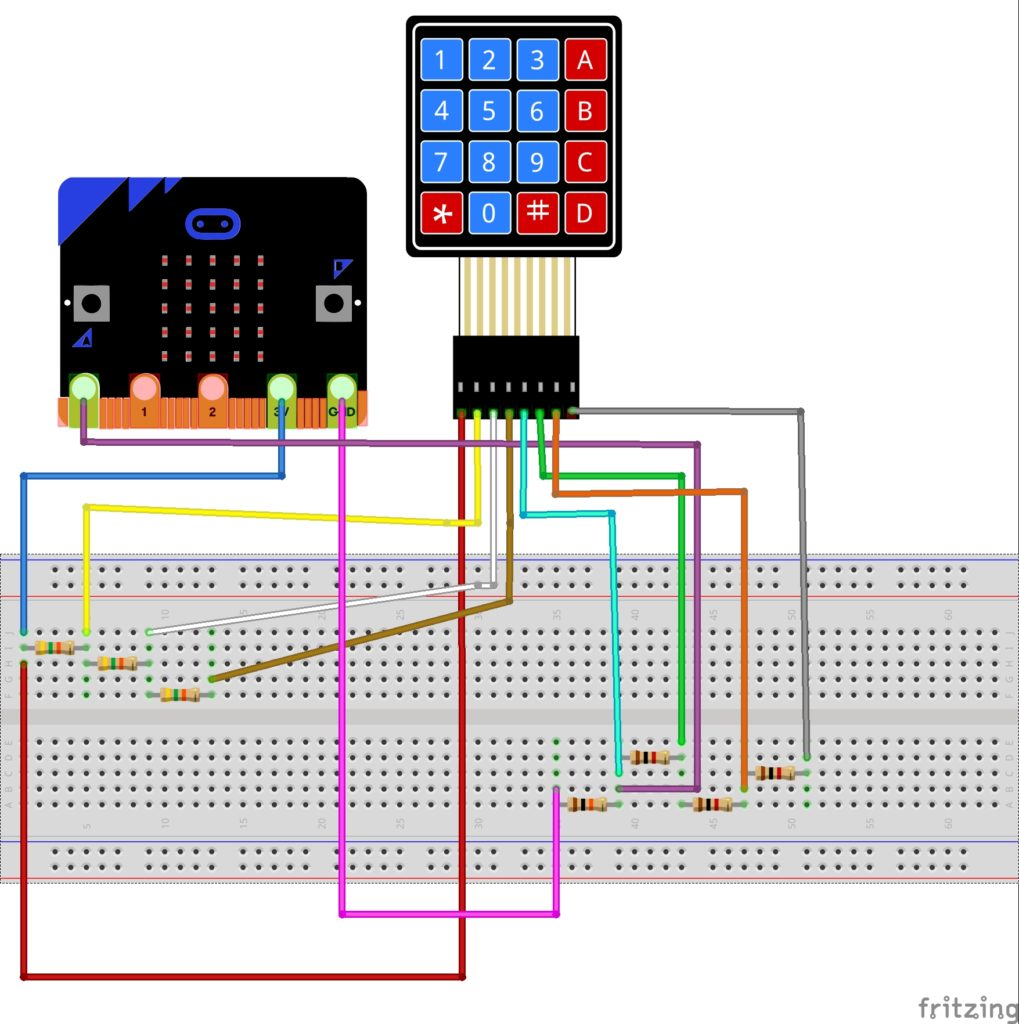
Attach the 3 pins of the Servo motor to P2 of the breakout board
Attach Ground (Black pin) of the Micro:bit to the 10kOh resistor
Attach the 3V (Red pin) to the 5k Ohm resistor
Attach A0 (Yellow pin) to the point between the 10k Ohm Resistor and 1k Ohm resistor
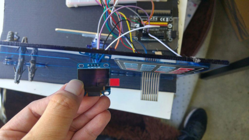
Connect GND,VCC,SCl and SDA of the breakout board to GND,VCC,SCl and SDA of the OLED respectively.
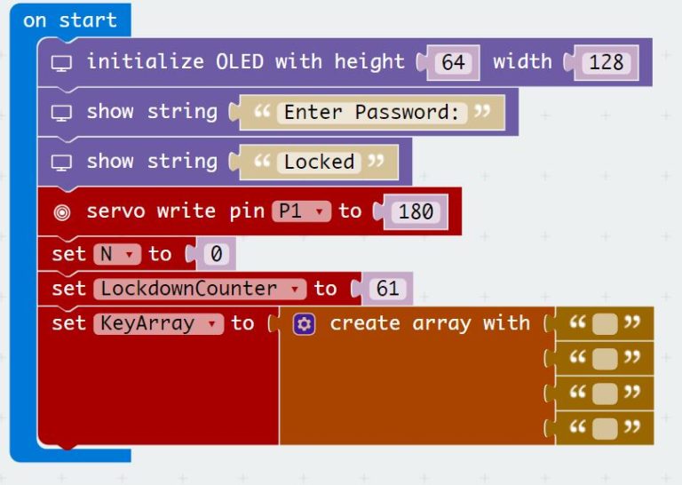
On start we have to:
Initialize the servo to position 180 (Locked Position)
Initialize the OLED display
Initialize a 4×1 array
Initialize the lockdown counter
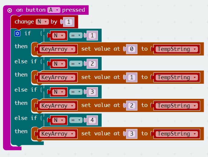
Button A acts as the enter character button
Every time you press a key on the 4×4 keypad you have to press Button A in order to key in a 4 digit Number
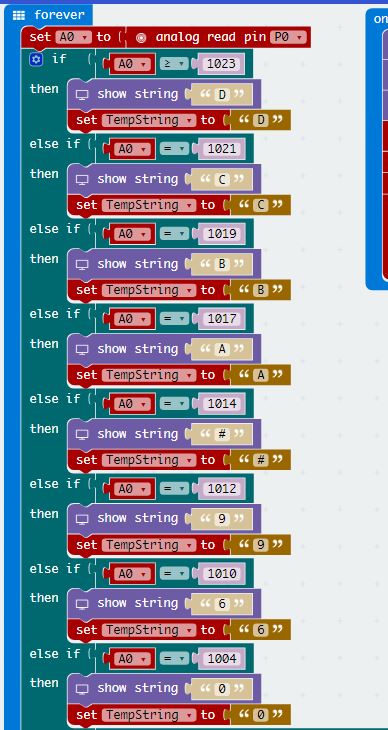
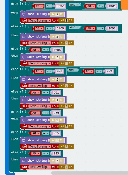
Next, we need to set up the micro:bit to detect the key presses!
Each key press corresponds to a unique analog value from 0 to1023 by using the driver circuit
The analog value can be read using the analog read function
The value in the character is stored in the “TempString” variable
The code block is quite long,so the download link is provided below.
Button B acts as the final “Enter” button
Pressing button B causes the program to check if the entered string is equal to “369#” using the compare block
if the answer is 0 it means that the strings are equal.If it is 1,then the strings are not equal
The number of wrong Attempts will increase by 1 every time an intruder enters the wrong password
Once 3 wrong attempts are detected,the program will enter a loop for 60 seconds
To reset the number of attempts and the characters entered,press Button A+B
The reset button also resets the servo to the “Locked Position”
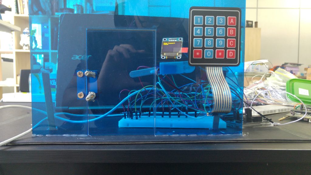
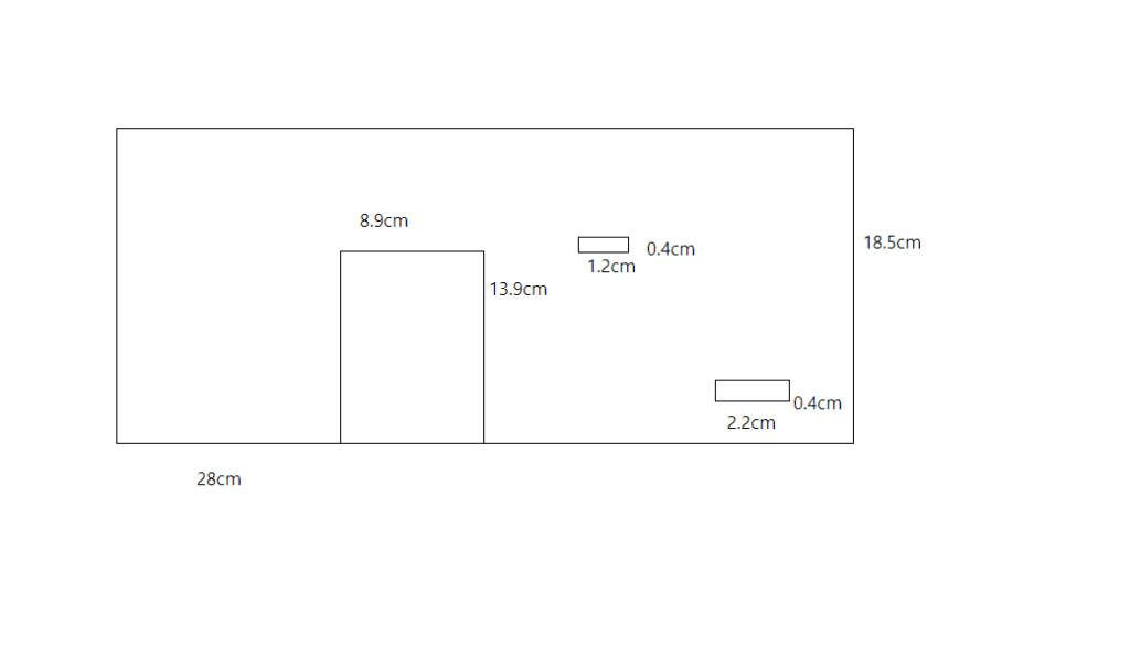
Using a laser cutter cut out 18.5cm by 28cm of 3mm acrylic
If you do not have acrylic you can use cardboard instead
cut out slots for the OLED as well as the keypad wires
Drill/poke holes forthe door hinge and use screws to fasten the door
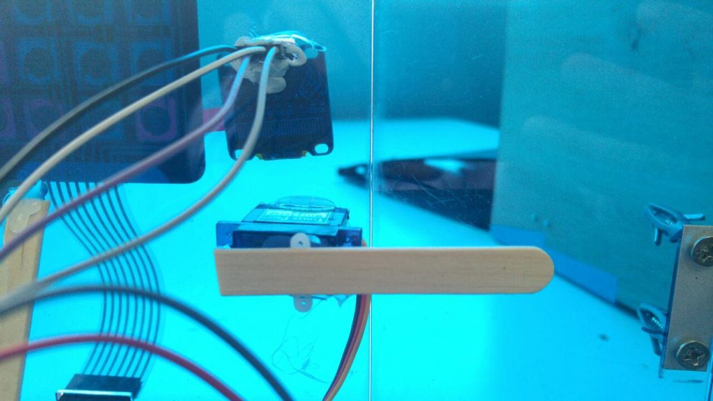
Attach an ice-cream stick to the servo.This will serve as the lock
Glue the servo with the ice-cream stick on the other side of the door
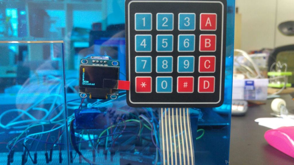
Each time you press a key,the corresponding character will appear on the OLED
To unlock the door key in 3,Button A,6,Button A,9,Button A,#
Then press button B
To reset press A+B
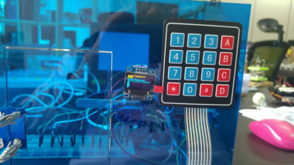
If you try to enter the wrong password three times the OLED will display a lockdown timer.You will only be able to enter the password after 60 seconds have passed.
Congratulations! You have made your own micro:bit door.