MicroPython
Micro:bit Tinker Kit ComponentsGetting Started
Pre-coding:
- Get hold of a Micro:bit Tinker Kit
- Download the Mu editor
- Before each project, write “from microbit import * ”
LED
Let the LED be connected to pin0
| Command | Usage |
|---|---|
| pin0.read_digital() | Check if LED is lighted or not pin0.read_digital() = 0 # means LED is not lighted pin0.read_digital() = 1 # means LED is lighted |
| pin0.write_digital(value) | Turn LED on or off pin0.write_digital(1) # lights LED pin0.write_digital(0) # turns LED off |
Example: Blink
Pin Layout
- LED: Pin0

from microbit import *
import time

# pins
LED_PIN = pin0

while True:
    LED_PIN.write_digital(1)  # turns on LED
    time.sleep(0.5)  # delays the next line of code for 0.5s
    LED_PIN.write_digital(0)  # turns off LED
    time.sleep(0.5)  # delays the next line of code for 0.5s
For more about digital signals click here
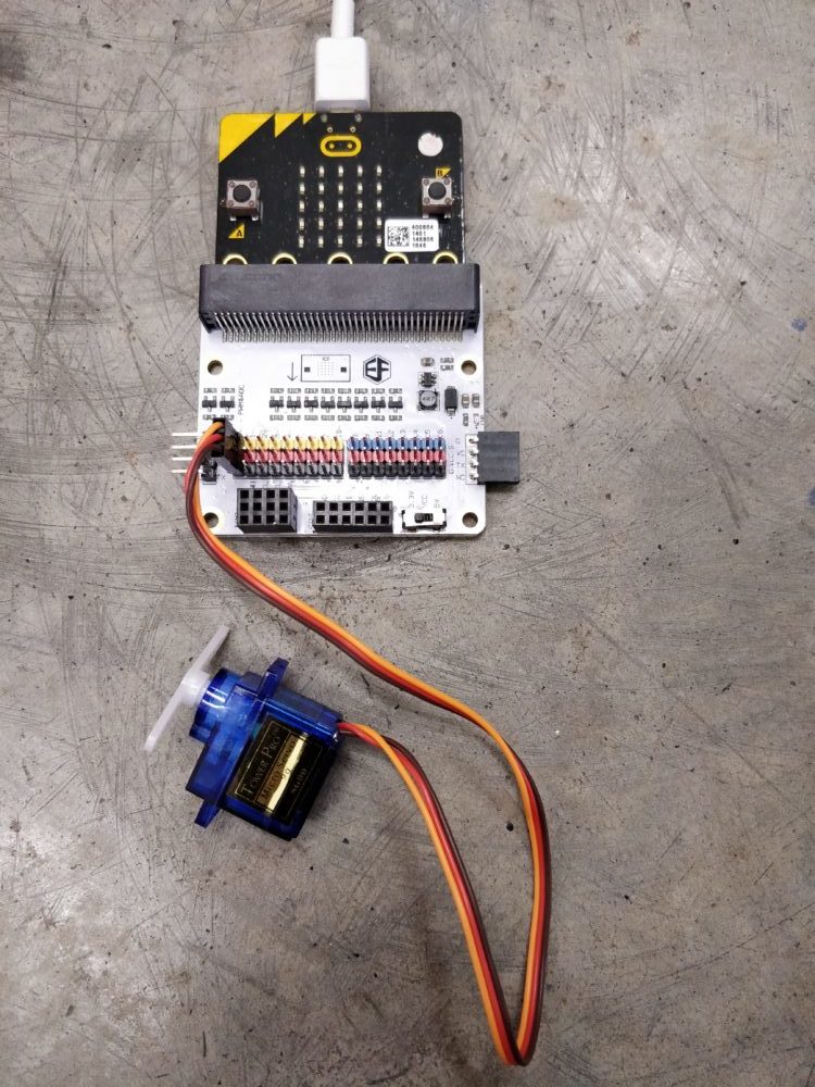
Mini Servo
Additional Library: servo.py
(adapted from https://github.com/microbit-playground/microbit-servo-class)
Using Additional Libraries:
Option 1:
- Copy and paste the code in the file above at the top of your code
Option 2 (adapted from https://github.com/microbit-playground/microbit-servo-class):
- Download the file in the link above and save it to the /mu_code/ directory in the root of your home directory
- Flash your code that is using the servo to mu
- An error message will scroll across the screen about the lack of the servo module.
- Once it has finished, click the ‘files’ icon in mu and upload the servo.py file to your microbit.
- Press reset on your microbit. When the program runs again it will load the module.
To initiate the servo, write: “servo_name = Servo(pin0) # attach servo to pin0”
| Command | Usage |
|---|---|
| servo_name.write_angle(angle) | Changes the angle position of the servo
Eg. |
Example: Sweep
Pin Layout
- Mini Servo: Pin0
from microbit import *
from servo import Servo
import time

# pins
Servo_pin = pin0

# initiate servo
servo = Servo(Servo_pin)

servo.write_angle(0)  # restart servo position

# main code
while True:
    servo.write_angle(180)  # changes servo position to 180
    time.sleep(1)  # delays the next line of code by 1s
    servo.write_angle(0)  # changes servo position back to 0
    time.sleep(1)  # delays the next line of code by 1s
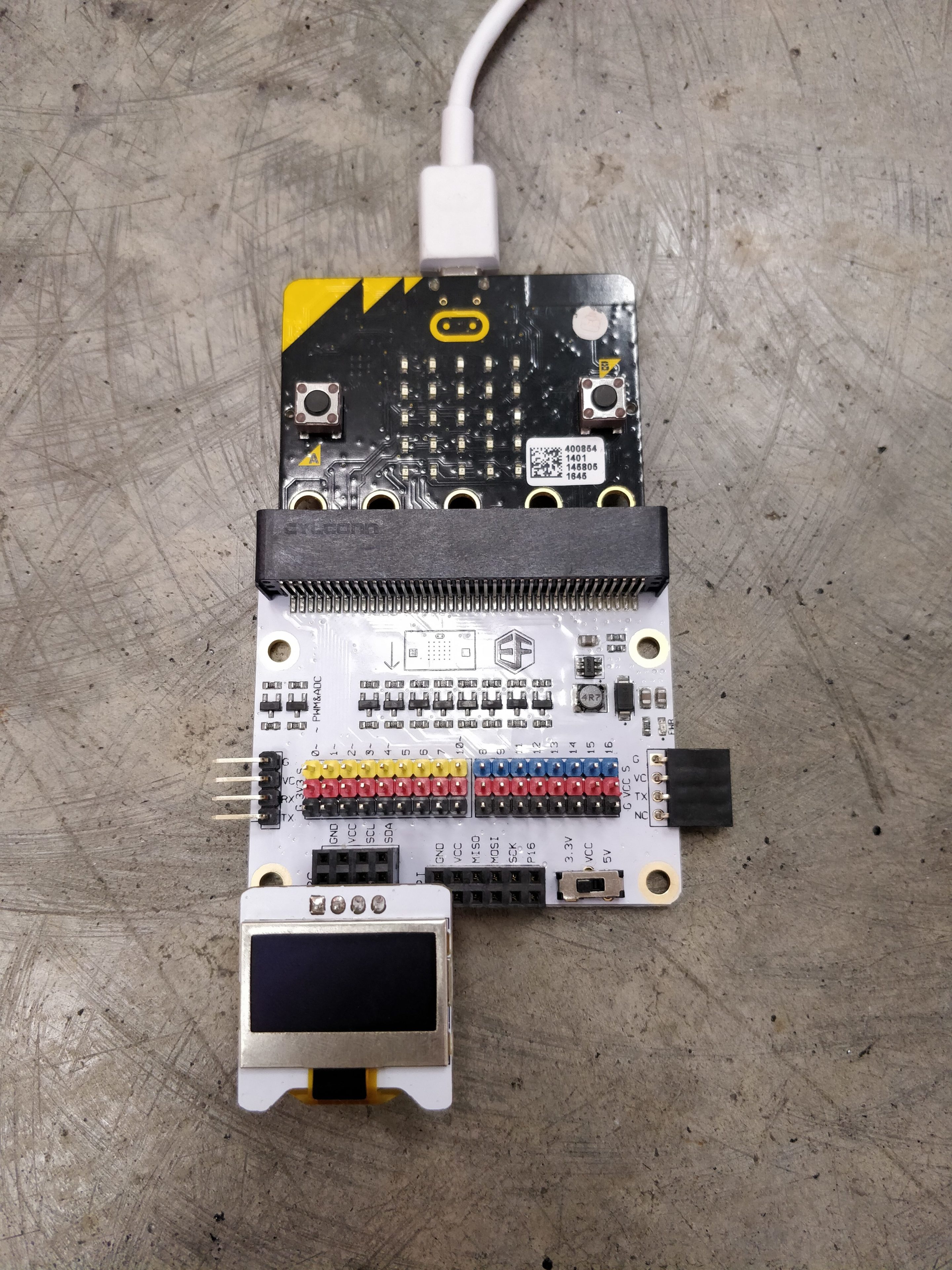
OLED
Additional Library: oled.py
Using Additional Libraries: Copy and paste the code in the file above at the top of your code
Initiating the OLED: from oled import *
| Command | Usage |
|---|---|
| oled_add_text(x, y, text) | Writes a string on the OLED screen Eg oled_add_text(0, 0, “Hello”) # prints Hello at the top left corner of the OLED screen |
| oled_clear_screen() | Clears the OLED screen |
Example: Hello World!
Pin Layout
- OLED: i2c
# Adapted from https://github.com/fizban99/microbit_ssd1306

from microbit import i2c, Image

OLED_ADDR = 0x3c
oled_screen = bytearray('b\x40') + bytearray(512)

def oled_initialize():
    for c in ([0xae], [0xa4], [0xd5, 0xf0], [0xa8, 0x3f], [0xd3, 0x00], [0 | 0x0], [0x8d, 0x14], [0x20, 0x00], [0x21, 0, 127], [0x22, 0, 63], [0xa0 | 0x1], [0xc8], [0xda, 0x12], [0x81, 0xcf], [0xd9, 0xf1], [0xdb, 0x40], [0xa6], [0xd6, 1], [0xaf]):
        i2c.write(OLED_ADDR, b'\x00' + bytearray(c))

def oled_set_pos(col=0, page=0):
    i2c.write(OLED_ADDR, b'\x00' + bytearray([0xb0 | page]))
    c1, c2 = col * 2 & 0x0F, col >> 3
    i2c.write(OLED_ADDR, b'\x00' + bytearray([0x00 | c1]))
    i2c.write(OLED_ADDR, b'\x00' + bytearray([0x10 | c2]))

def oled_clear_screen(c=0):
    global oled_screen
    oled_set_pos()
    for i in range(1, 513):
        oled_screen[i] = 0
    oled_draw_screen()

def oled_draw_screen():
    global oled_screen
    oled_set_pos()
    i2c.write(OLED_ADDR, oled_screen)

def oled_add_text(x, y, text):
    global oled_screen
    for i in range(0, min(len(text), 12 - x)):
        for c in range(0, 5):
            col = 0
            for r in range(1, 6):
                p = Image(text[i]).get_pixel(c, r - 1)
                col = col | (1 << r) if (p != 0) else col
            ind = x * 10 + y * 128 + i * 10 + c * 2 + 1
            oled_screen[ind], oled_screen[ind + 1] = col, col
    oled_set_pos(x * 5, y)
    ind0 = x * 10 + y * 128 + 1
    i2c.write(OLED_ADDR, b'\x40' + oled_screen[ind0 : (ind+1)])

oled_initialize()
oled_clear_screen()

oled_add_text(0, 0, "Hello World!")
Passive Buzzer
Addition library: type: “import music” at the top of your code
Musical notations:
Adapted from https://microbit-micropython.readthedocs.io/en/latest/music.html
Structure (case insensitive): NOTE[octave][:duration]
Eg.
a4:1 # note A in octave 4 that lasts for 1 tick (an arbitrary duration set by a tempo setting function)
R:2 # R signifies a rest (ie silence) which in this case lasts for 2 ticks
Accidentals (sharps and flats):
Sharp – #
Flat – b (lower case)
Eg. a#4:1 # note A sharp in octave 4 that lasts for 1 tick
Note:
- Octave and duration parameters carry over to the next note until re-specified.
- The default octave = 4 and the default duration = 4
The octave definitions follow the table of note frequencies in the following link
Let the buzzer be connected to pin0
| Command | Usage |
|---|---|
| music.set_tempo(ticks=4, bpm=120) |
Sets the tempo, where ticks and bpm (beats per min) are integers.
The indicated number of ticks lasts for 1 beat and each beat is played at a certain frequency per minute (expressed in BPM) Eg. |
| music.get_tempo() | Obtain the current tempo as a tuple of integers – (ticks,bpm) |
| music.play(music, pin=microbit.pin0, wait=True, loop=False) | Plays a tune.
The duration and octave values are reset to their defaults before the music is played. music can be a string: must be a single note eg “a1:4” You can overwrite the default music pin at pin0 If wait = True, the music will play to the end before the next line of code is executed If loop = True, the music repeats until music.stop() is called or the blocking call is interrupted The music module also contains built in melodies that can be played using the following structure: Eg music.play(music.ODE) More built in melodies can be found in the following link under Built in Melodies |
| music.pitch(frequency, duration=-1, pin=microbit.pin0, wait=True) | Plays the pitch at the integer frequency in ms.
Only one pitch can be played at a time. If wait = True, the pitch will play to the end before the next line of code is executed If duration is negative, the pitch will play continuously until the blocking call is interrupted, a new frequency is set or music.stop() is called |
| music.stop(pin=microbit.pin0) | Stops all the music playing on a given pin (default at pin0) |
| music.reset() | Resets the following values
|
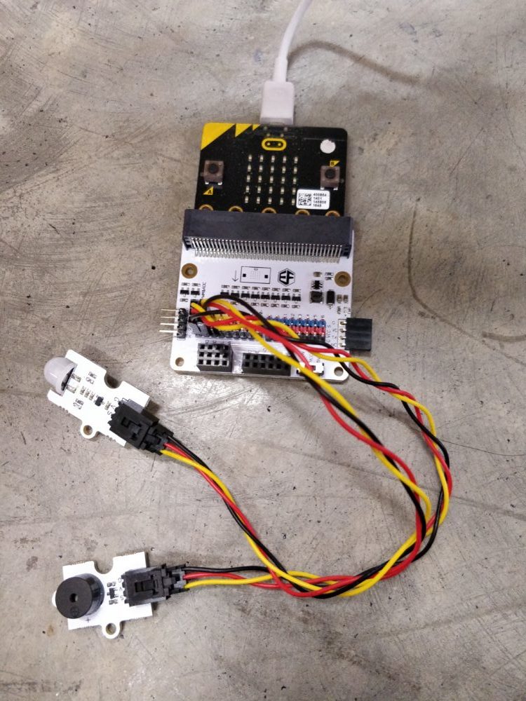
Example: Doorbell
Pin Layout
- Passive buzzer : pin0
- Crash sensor: pin1

from microbit import *
import music

# pins
Buzzer_pin = pin0
CrashSensor_pin = pin1

# set up crash sensor
CrashSensor_pin.set_pull(CrashSensor_pin.PULL_UP)

while True:
    # if crash sensor is pressed, play a note, if not stop the music
    if CrashSensor_pin.read_digital() == 1:
        music.stop()
    else:
        music.play("c5:4")
PIR Sensor
Essentially a motion detector
Let the PIR sensor be connected to pin0
| Command | Usage |
|---|---|
| pin0.read_digital() | Check if PIR sensor detects motion or not pin0.read_digital = 0 # means no motion detected pin0.read_digital = 1 # means motion detected |
Example: Motion Alarm
Pin Layout
- Passive buzzer: Pin0
- PIR sensor: pin1
from microbit import *
import music

# pins
buzzer_pin= pin0
PIRSensor_pin = pin1

while True:
    # if motion is detected play a sound, if not stop the music
    if PIRSensor_pin.read_digital() == 0:
        music.stop()
    else:
        music.play("c5:4", wait=False)
For more about digital signals click here
Crash Sensor
Note: always set the pull of the pin connected to the crash sensor to PULL_UP by writing:
“pin0.set_pull(pin0.PULL_UP) # connect the crash sensor to pin0”
To learn more about pull-up resistors, click here
Let the crash sensor be connected to pin0
| Command | Usage |
|---|---|
| pin0.read_digital() |
Check if crash sensor is pressed or not pin0.read_digital = 0 #means crash sensor is pressed pin0.read_digital = 1 #means crash sensor is not pressed |
Example: LED switch
Pin Layout
- Crash sensor: Pin0
- LED: pin1
from microbit import *

# pins
CrashSensor_pin = pin0
LED_pin = pin1

# set up crash sensor
CrashSensor_pin.set_pull(CrashSensor_pin.PULL_UP)

# main code
while True:
    # if crash sensor is pressed, LED lights up
    if CrashSensor_pin.read_digital() == 0:
        LED_pin.write_digital(1)

    # if crash sensor is not pressed, LED does not light up
    else:
        LED_pin.write_digital(0)
For more about digital signals click here
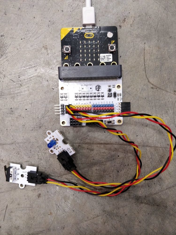
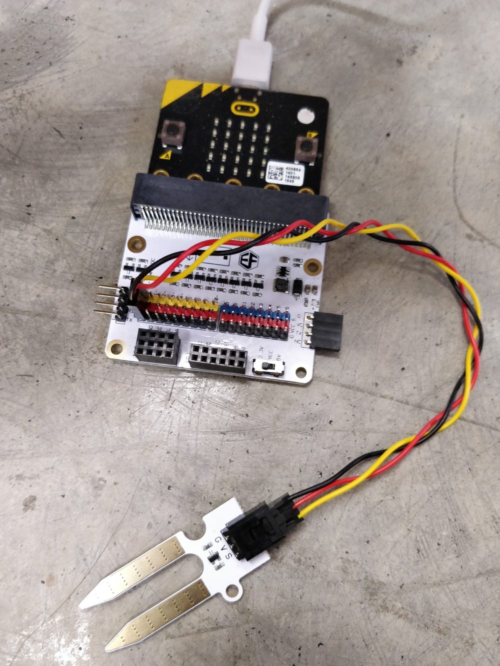
Soil Moisture Sensor
Let the soil moisture sensor be connected to pin0
| Command | Usage |
|---|---|
| pin0.read_analog() | Gets the moisture level of the surroundings on a scale from 0 to 1023 (3.3V) |
Example: Display soil moisture
Pin Layout
- Soil Moisture Sensor: pin0
from microbit import *
import time

# pins
soilMoistureSensor_pin = pin0

while True:
    soil_moisture = soilMoistureSensor_pin.read_analog()
    display.scroll(soil_moisture)
    time.sleep(1)
For more about analog signals click here
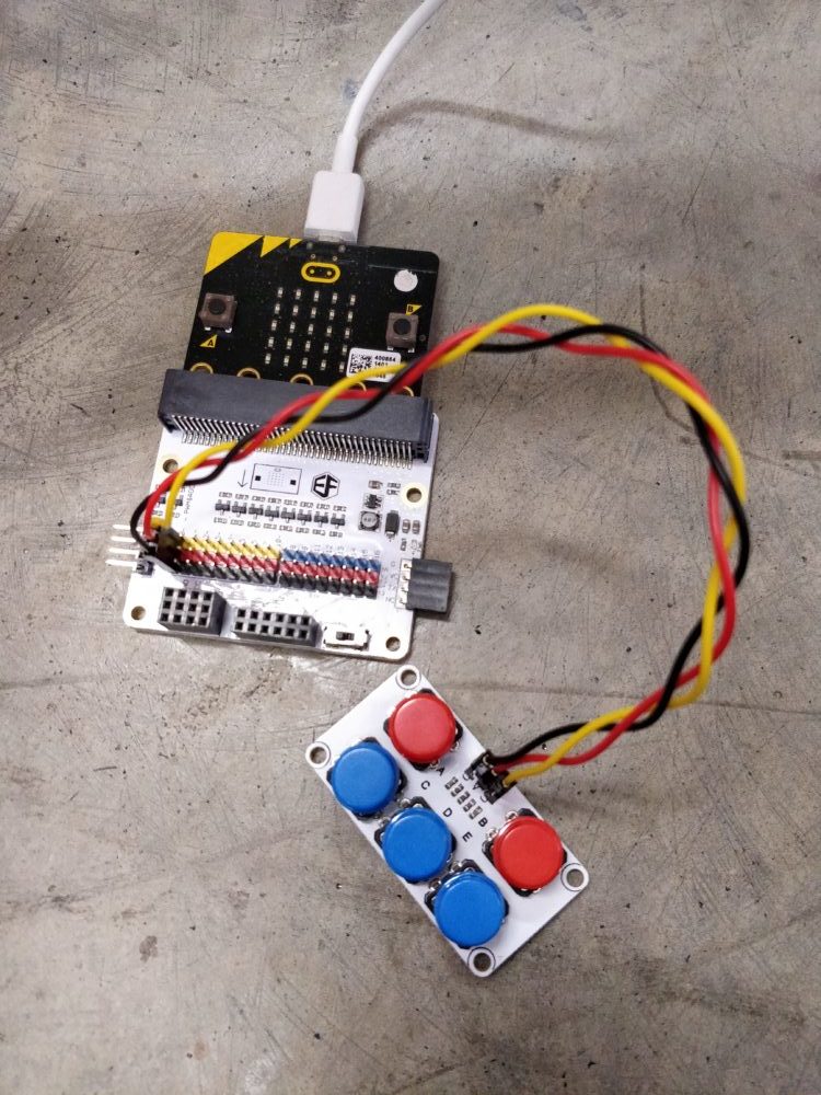
ADKeypad
About the ADKeypad:
The ADKeypad has 5 buttons labeled from A to E. When each button is pressed, they give unique analog signals.
By experimenting on our side, the buttons give the following range of signals.
- A – 0 to 10
- B – 45 to 55
- C – 90 to 100
- D – 135 to 140
- E – 535 to 545
*disclaimer: your ADKeyboard might produce different results, do try to find out the values for yours
Let the ADKeypad be connected to pin0
| Command | Usage |
|---|---|
| pin0.read_analog() | Gets the signal from the ADKeyboard ranging from 0 to 1023 (3.3V) |
Example: Image Pop-up
Pin Layout
- ADKeypad: pin0
from microbit import *

# pins
ADKeypad_pin = pin0

while True:
    # buttonA
    if ADKeypad_pin.read_analog() > 0 and ADKeypad_pin.read_analog() < 10:
        display.show(Image.SILLY)

    # buttonB
    if ADKeypad_pin.read_analog() > 45 and ADKeypad_pin.read_analog() < 55:
        display.show(Image.HAPPY)

    # buttonC
    if ADKeypad_pin.read_analog() > 90 and ADKeypad_pin.read_analog() < 100:
        display.show(Image.SKULL)

    # buttonD
    if ADKeypad_pin.read_analog() > 135 and ADKeypad_pin.read_analog() < 140:
        display.show(Image.PITCHFORK)

    # buttonE
    if ADKeypad_pin.read_analog() > 535 and ADKeypad_pin.read_analog() < 545:
        display.show(Image.DUCK)
For more about analog signals click here
Potentiometer
Let the potentiometer be connected to pin0
| Command | Usage |
|---|---|
| pin0.read_analog() | Get an indication of how much the knob is turned by, on a scale from 0 to 1023 (3.3V) |
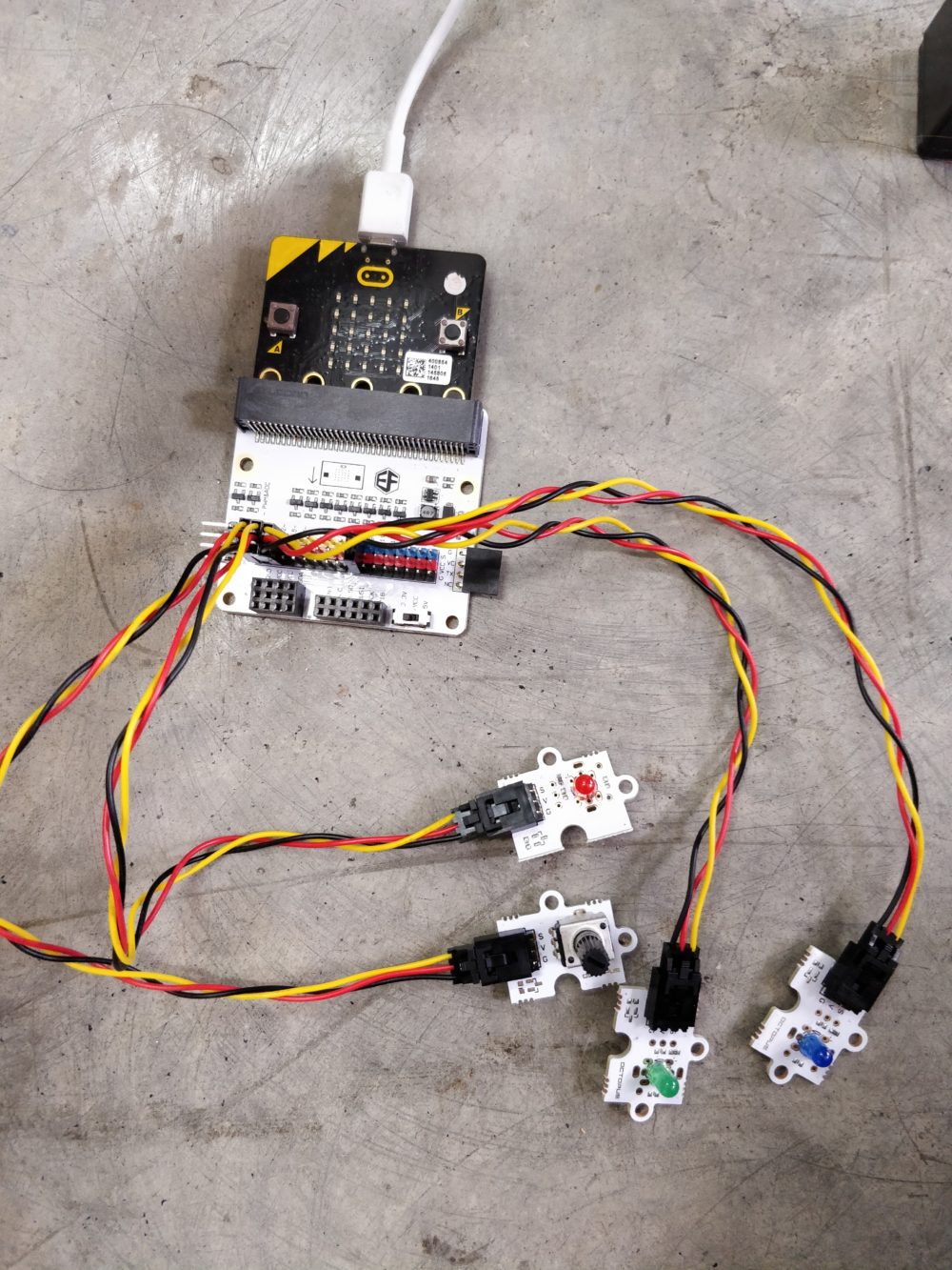
Example: Light Switch
Pin Layout
- Potentiometer: pin0
- Red LED : pin1
- Green LED: pin2
- Blue LED: pin8
from microbit import *

# pins
p_pin = pin0  # potentiometer_pin
redLED_pin = pin1
greenLED_pin = pin2
blueLED_pin = pin8

while True:
    # turn on red led only
    if p_pin.read_analog() > 0 and p_pin.read_analog() <= 341:
        redLED_pin.write_digital(1)
        greenLED_pin.write_digital(0)
        blueLED_pin.write_digital(0)

    # turn on green led only
    if p_pin.read_analog() > 341 and p_pin.read_analog() <= 682:
        redLED_pin.write_digital(0)
        greenLED_pin.write_digital(1)
        blueLED_pin.write_digital(0)

    # turn on blue led only
    if p_pin.read_analog() > 682 and p_pin.read_analog() <= 1023:
        redLED_pin.write_digital(0)
        greenLED_pin.write_digital(0)
        blueLED_pin.write_digital(1)
For more about analog signals click here
Find out more
For a more comprehensive explanation of MicroPython, visit the official documentation here!