

Editor’s note: Read Parts 1, 2, and 3 first for some background on what we call “Viennale”: the Singapore Pavilion for the Venice Biennale, No More Free Space, a project we undertook in collaboration with the Singapore University of Technology & Design. Concluding the story with a tale of extreme signal processing is Melvin, our intern who’s just started school at NTU:
Steven and Sarah’s plan was to use CE-certified lights for the panels so as to ensure there would not be any safety issues (almost 1000W of power) whilst adhering to European law (we’re a law-abiding company 😄).
However, the lights’ remotes had no obvious programming interfaces, so there was no easy way to control them with a computer. I was tasked to develop that interface.
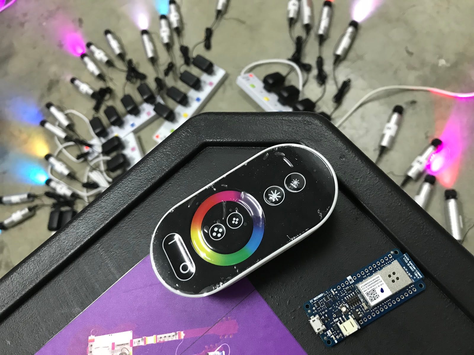
The “Light Sabres” (background), the “Light Sabre” remote (foreground), and the Arduino MKR1000 (right).
I started out by disassembling the casing, but instead of the push-buttons and potentiometer I was expecting, I was met with… capacitive buttons and rings. Luckily, the internet had tons of documentation on how capacitive touch sensors worked.
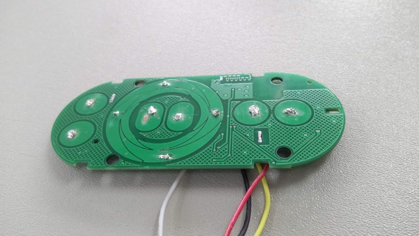
Strange green PCB that definitely has not been tampered with
How do capacitive touch sensors work?
An average human body has a capacitance of 100 picofarads. Thus, when you touch one of the pads, you have essentially “added” a 100 picofarad capacitor to ground. While this is happening, the touch IC is constantly sending sawtooth signals at a fixed frequency every once in awhile.
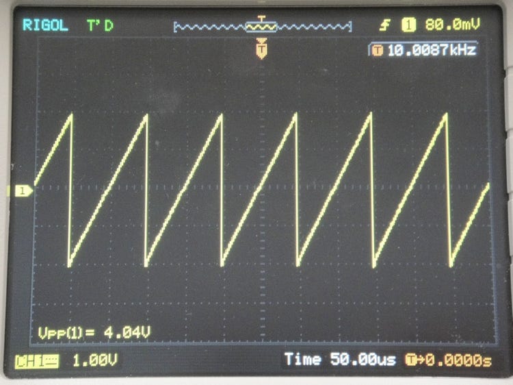
Example of a sawtooth signal
A capacitor is basically a small and fast charging battery. So when the voltage is rising, it takes longer to rise to the maximum as it’s “charging the battery”. By extension, when the voltage is decreasing, it also takes longer to reach the minimum as the battery is “discharging” into the circuit (A more eloquent explanation at this YouTube video).
Since the time taken to discharge and charge is increased, this means there is also an increase in the frequency of the sawtooth signal. The IC detects this change in frequency and once it passes a certain threshold, a button is flagged as being pressed.
TLDR: Our body is able to store and release some electricity. When we touch the sensor, it decreases the frequency of the electrical signal that the sensor sends out. The microchip senses this change in frequency.
First Prototype
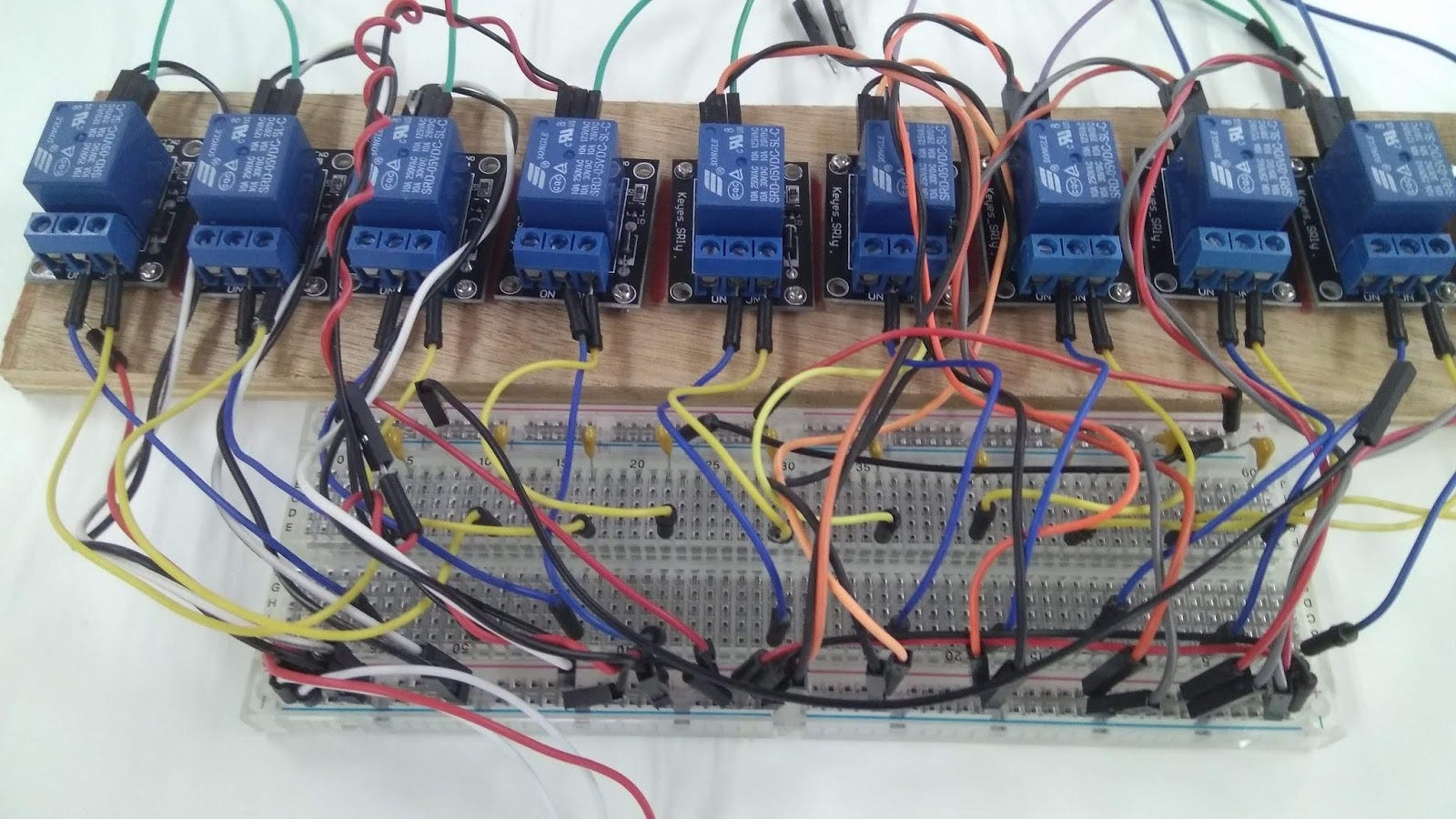
“What did I sign up for in this internship again?”
My first “bright” idea (pictured above) was to literally simulate touches by connecting 100 picofarad capacitor to the pads. I decided to use relays as switches because transistors have capacitance themselves (which would “trigger” the button press). Surprisingly, the device worked! Unfortunately, it wasn’t able to emulate the smooth colour transitions of the capacitive ring. Reliability and space usage also left a lot to be desired, ahem.
Second Prototype
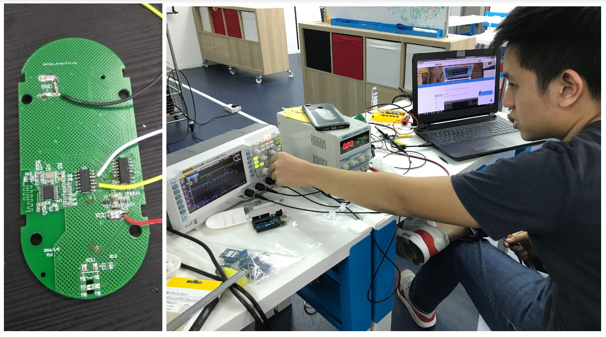
Left: Other side of the PCB. Right: using the oscilloscope to probe the board
Looking on the other side of the PCB, there were 3 chips. I theorised that these were a capacitive chip, a micro-controller, and a wifi chip. Why didn’t I just look up the data sheets? It turns out the manufacturer actually ground off the chips models in an effort to thwart their competitors from copying their design (is this a common practice?). Even when we contacted them directly, they were unwilling to disclose the models of the chips.
It was pretty challenging dealing with SMD (surface-mount device) electronics. Even simple probing can be quite challenging. I had to learn how to solder jumper wires on the tiny pins (tips: blue-tac to hold stuff, use a really hot iron, pre-tin everything, and use lots of flux!!) just to be able to probe them.
After lots of investigation (ahem, trial and error), I managed to reverse-engineer the pins that were responsible for communication between the microcontroller and the capacitive touch IC and also the protocol running on it. I decided to hijack this part as the button presses would predictability activate certain signals on the oscilloscope.
Decoding the Electrical Gibberish
Having access to what I thought was the data, clock and sleep lines was just the beginning, more importantly, I had to use my secret “sophisticated” method to totally hack the code.
Imma hackerrrrrr. Source.
So… my method was to primitively activate a button and then frantically write down the bit value for each clock edge. I would then proceed to pull my hair out in trying to match the binary data to some sort of message.
After two (or what felt like an eternity of) days of trying to figuring out the protocol, a very kind Steven asked a magical question: “err… did you know we have a logic analyser?”
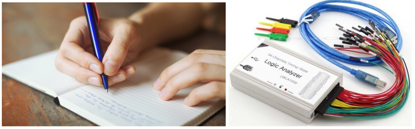
Writing and brain vs logic analyser. No contest. Source; source.

A logic analyser was the perfect tool for the task, it even had a I2C decoder which decoded what each bit meant—namely, addresses, read or write, and the actual data payload.
Since I could now read the signals, the next step was to write. To do that, I had to disconnect the existing wiring, an irreversible step. Luckily, the firmware I wrote worked! While Steven continued to worked on the web server so we could communicate with the lights wireless, I improved upon the firmware controlling the remote.
Simultaneously, the shipment of lights and remotes came in and I was in charge of unpacking, checking, unpairing (with the wrong remotes) , pairing (with the right remotes) , labeling, re-packing and shipment of almost 220 remotes! I have a newfound respect for delivery men and QC officers after 2 days of hard work.
At this point, I’ll let the pictures do the talking:
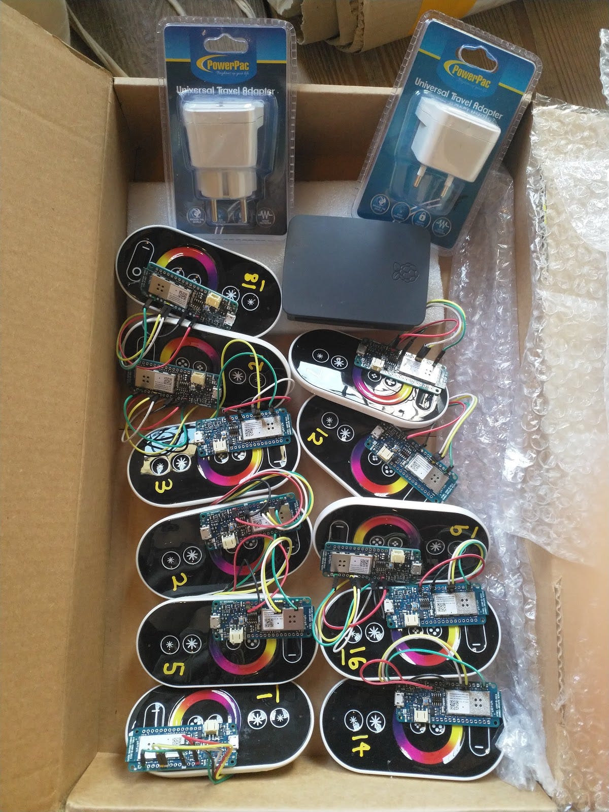
Precisely soldered connections, ready to ship.
And we were off to Venice to complete the set-up!
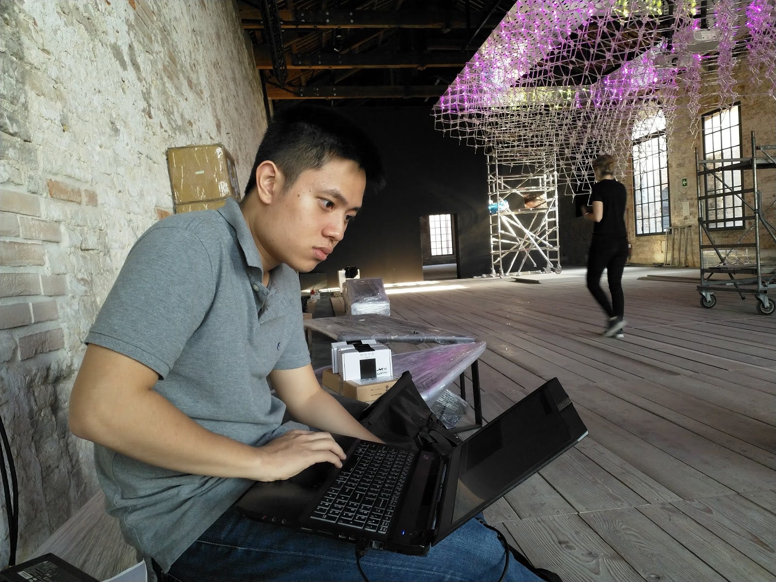
Fixing bugs in Venice
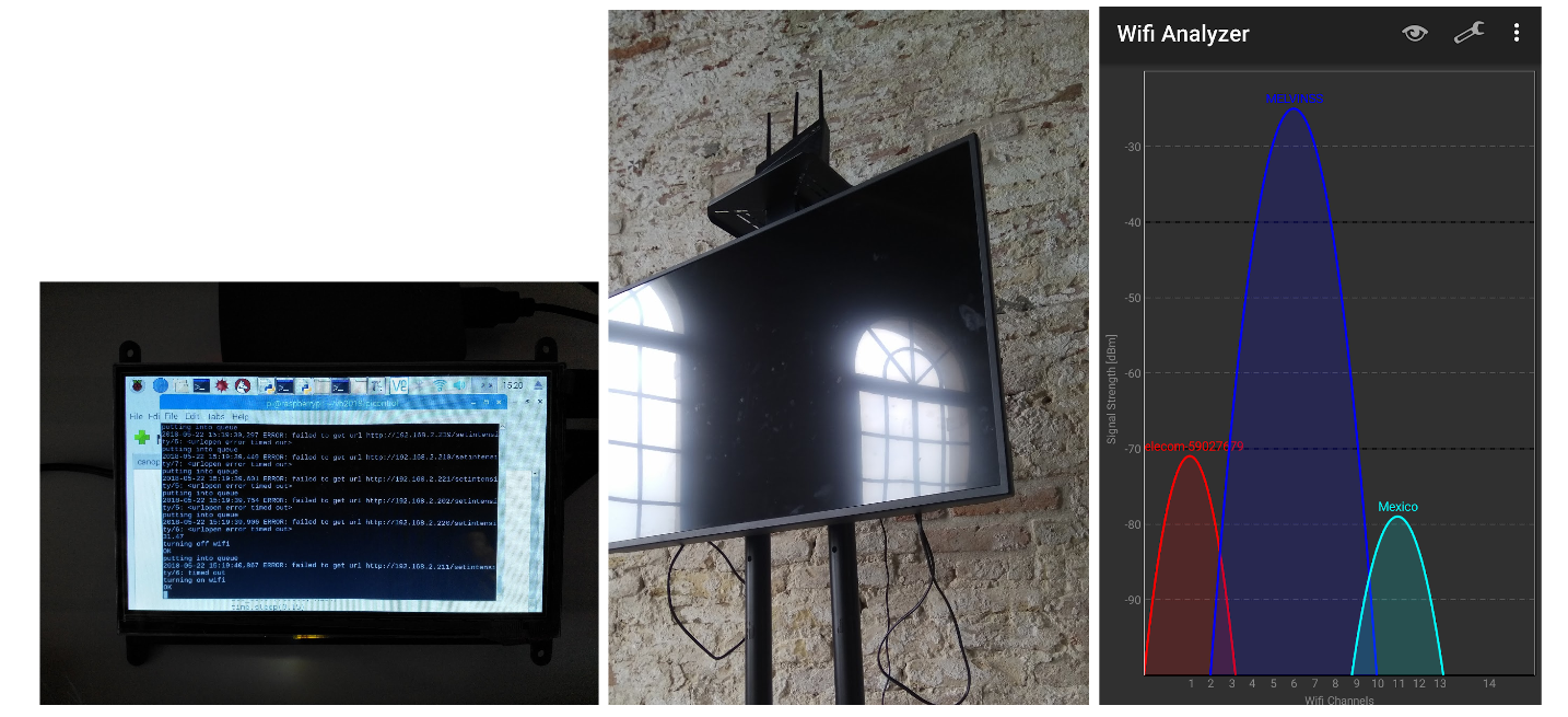
We had weird URL timeout errors, which were fixed by just repositioning the router and optimising the channel width.
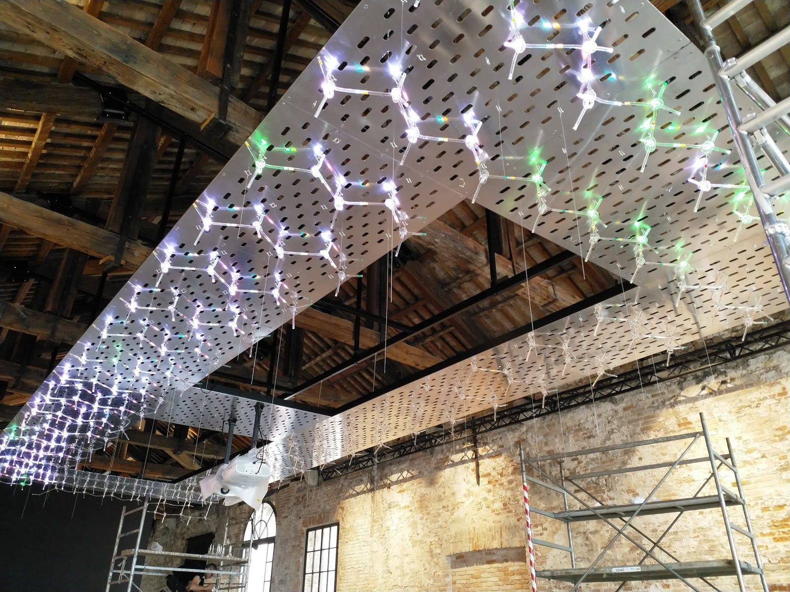
We introduced a interlacing pattern & a delay between commands to reduce interference between remotes.
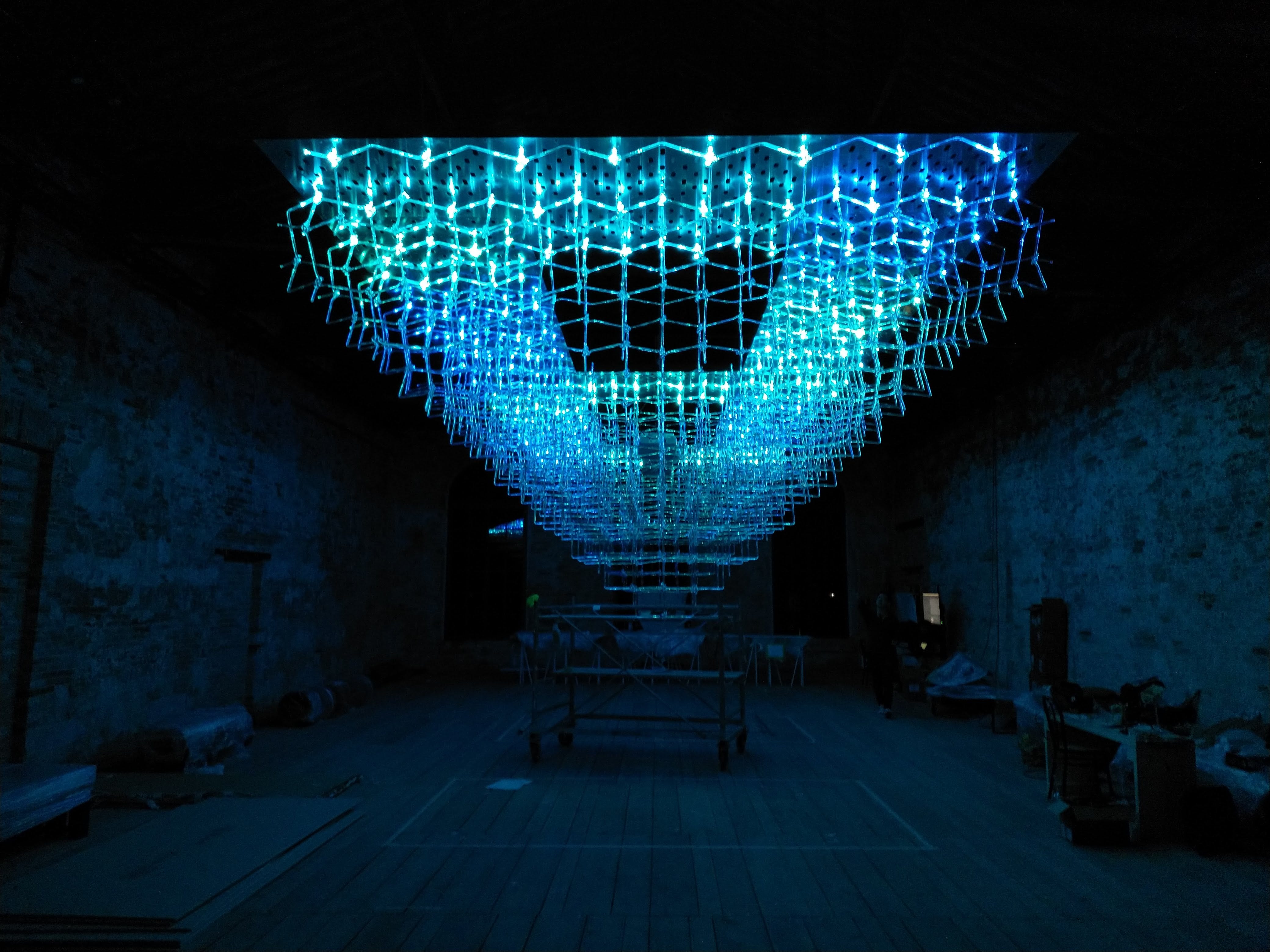
And that’s it! I think the launch went well, and the exhibit is on-going until November 2018. Look up the official website at nomorefreespace.com for news.
Thank you Tinkertanker for giving me this opportunity (I tried my best)! I would like to specially thank Sarah and Steven for rallying together when times were tough!