

Editor’s note: Darius joined us as an intern over the summer of 2019, all the way from California in the US. Among other projects, we asked him to help update our OLED MakeCode extension for the micro:bit, and he did an awesome job—read on for details!
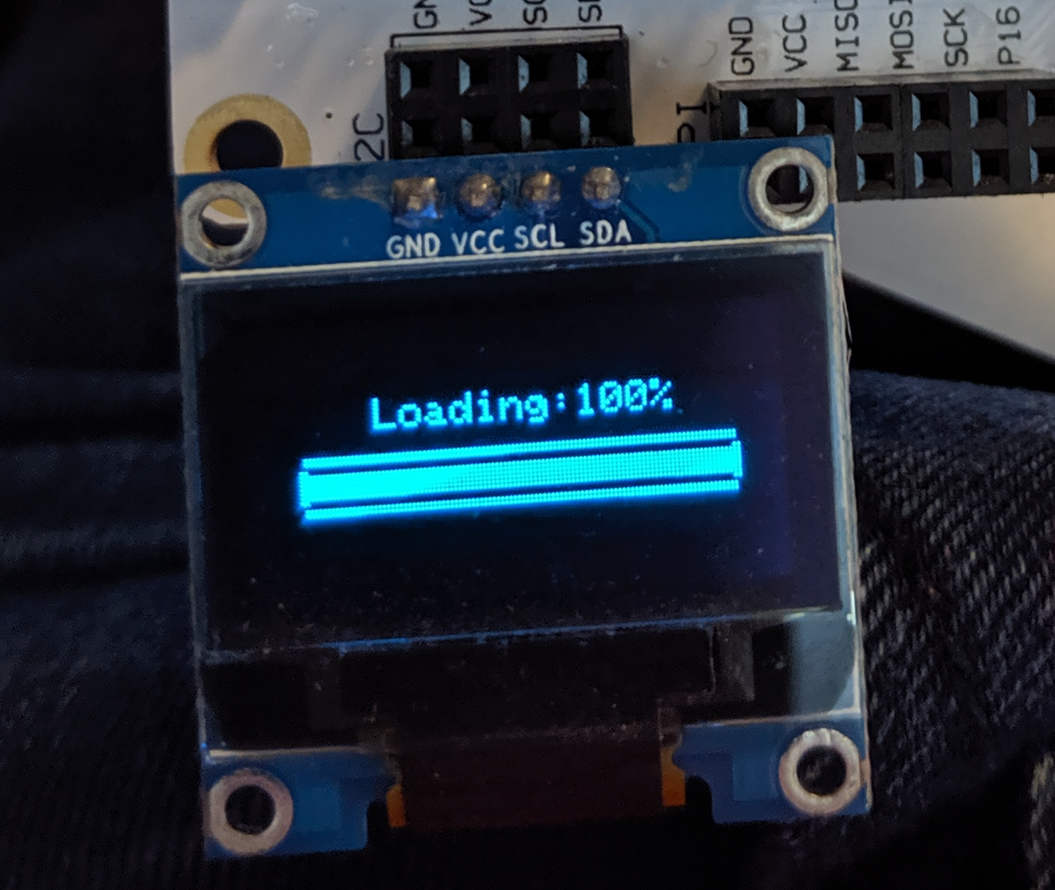
In case you don’t know, the I2C OLED is a small digital display which is useful for electronics projects. I wrote a micro:bit library to use the I2C OLED, and in doing so I had to learn a lot of specifics about how it works. For most projects these specifics won’t be at all important and you can just rely on a library to handle the details. However, if you are writing a library yourself or are just interested in esoteric part specifications, you’ll hopefully get something out of this.
How The OLED Draws
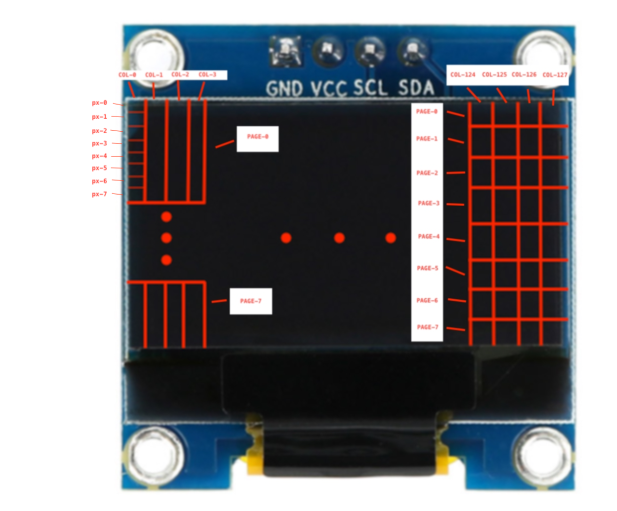
Diagram of the OLED pages and Columns
When I first was learning about the OLED, I assumed that I would draw to the screen by read and write to pixel addresses, similar to how one draws to the screen on a computer. However, the primary units of drawing with the OLED are not pixels but Pages and Columns. There are 8 pages which go from top to bottom of the screen, and 128 columns that go from left to right. A single Page-Column address corresponds to a vertical strip of 8 pixels, which must all be written at once. The OLED keeps track of the page-column address, and will read incoming byte into that address. A 1 corresponds to the pixel being on and a 0 corresponds to the pixel being off. Since there are 8 bits in a Byte, a single byte corresponds to all the pixels in a single column address. Once an address has been written too, the OLED will automatically move on to the next address.
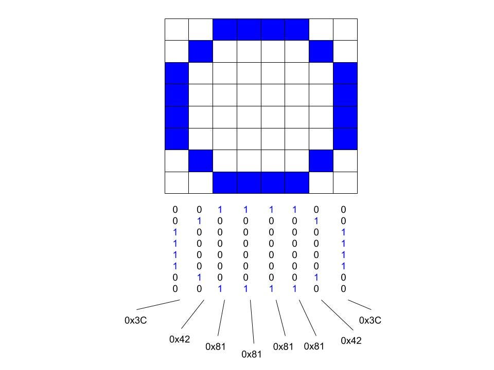
To Draw this circle, you would feed the OLED these bytes from left to right
In addition to the current page-column address, the OLED also stores two more coordinates called Start and End. These two page-column addresses define a square with Start in the upper-left corner and End in the lower-right corner. While writing or reading the screen, the current address will move continuously right until it reaches the edge of the rectangle, then wraps to the start of the next row. This allows you to write to the whole screen at once by setting the start to (0,0) and then end to (7,127). However, you don’t have to write to the whole screen at once. The OLED library I wrote preserves memory by not storing the entire screen at once, and instead writing to the specific 5x8 px block where the character was to be drawn. Also note, there are three different “addressing modes” which control how the page column address moves as you write or read. I am describing “horizontal addressing”, which is the most common.
How The OLED Reads
This is all very well and good, but how do you do any of this writing and addressing? The I2C OLED, as the name suggests, uses something called the I2C protocol. This is a hardware protocol use for communicating with simple electronic peripheries. It’s main advantage is the use of a Master-Slave system, which allows for one controller (the Master) to drive multiple devices (the Slaves) at the same time, each with their own address. I2C devices have 4 pins: Ground(GND), Power(VCC), Serial Data Line(SDL) and Serial Clock Line(SCL).
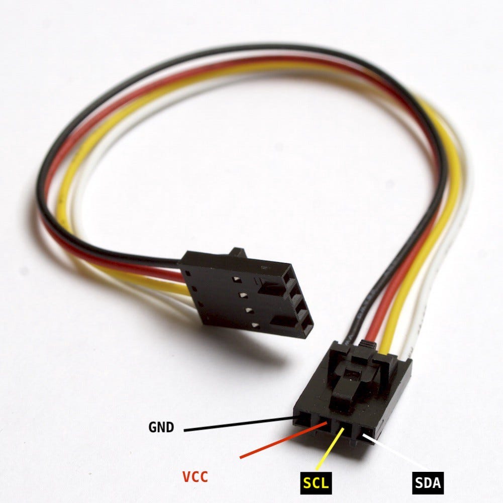
GND and VCC are kept at Low (zero volts) and High(usually either +5 or +3.3 volts) respectively, acting as a power supply. SDA and SCL are responsible for sending messages to and from attached I2C devices. The structure of a I2C message is as follows: SCL and SDA begin High, and the beginning of a message is marked by SDA going from High to Low, called the Start Condition. From there, SCL oscillates between High and Low, each oscillation being a bit read from SDA. I2C devices interpret these bits in blocks of 16. Each 16 bits consists of an 7 bit Slave Address, followed by a 1 bit Read/Write, followed by 8 bits of data. How this data is interpreted depends on the particular I2C device used. When all attached devices have been written to or read from, the SCL is held at High, and the SDA is brought High as well. This is called the Stop Condition.

The I2C protocol. S and P are the Start and Stop conditions. Each B is a 7 bit address + R/W, and each blue square is 8 bits of data.
Each kind of device has its own address, meaning that any number of devices, but only one of each kind, can be connected to the same Master. The OLED’s address is 0x3C for writing, and 0x3D for reading. The OLED interprets incoming data as a “Command” byte, followed by any number of data bytes. While this simplifies a little, 0x00 can be thought of as the command for “write this data to the current address”. There are commands for changing the address, changing the Start and End points, and many more settings. A full list of commands, as well as more information about the OLED, can be found here.
Closing Thoughts and Future Work.
When initializing an OLED for the first time, there are a bunch of settings that need to be set, each with an associated command. I must admit that I do not understand the full scope of what these settings do, and it’s possible that some interesting things could be done with more nuanced control over these settings. If you want to see the list of commands I used, you can check out the GitHub for my OLED library.
One addition I have considered for the OLED library is the introduction of new fonts with additional character sets such as Chinese or Korean. The current font I use is 5x7 px, and is stored as a string of blocks of 5 bytes, corresponding to rows of pixels in the character. This size was chosen so that a character would fit on a single page. Most bitmap fonts for Chinese don’t scale well below 16x16, but this would still allow for characters drawn across two pages at once. I was unable to find a font that would work well for this, but it seems like it should be doable.
Anyway, that’s all for my Deep Dive into the I2C OLED. I wish you the best of luck on whatever electronics project you work on next!